Building a Rasberry Pi Power Control Unit
In this post I detail the hardware, software, code and steps that I took to create the capability to remotely power cycle devices through the use of the GPIO pins on a Rasberry Pi to control both NO (Normally Open) and NC (Normally Closed) relays.
It is important to note that we will be using both NO and NC relays to allow for a more fault tolerant build. The RasPi will directly control NO relays that have a lower amperage rating. These relays will, in-turn, control a 12v current to another NC relay to allow for a power cycle of any device connected to the higher amperage rated NC relay.
We use an NC relay to power our actual devices so that even in the event of a controlling circuit failure the device will remain powered on. If we were using an NO relay there would be risk of power loss to the relay resulting in the NO to open and cause a loss of power to the main equipment.
Hardware
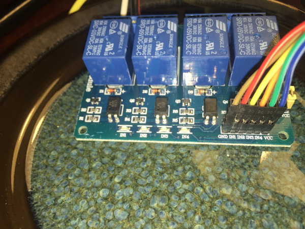
- 4 channel relay board with both NC and NO poles
- Amazon
- This is the relay module that interfaces directly with the GPIO on the raspi and will be responsible for controlling the higher load relay
- RasPi GPIO T-Cobbler
- Amazon
- Not required but useful for mapping GPIO pins easily for testing
- High capacity relays with both NC and NO poles
- Amazon
- Need to handle higher amperage as we will be pushing 8.5 through it for long periods of time at high usage times.
- NC Side of this does 30A @ 14VDC, should be adequate for MY project
- Breadboard Jumpers
- Amazon
- Used to connect RasPi to 4 channel relay board
- Power
- Ground
- 4x Control Channels
- Misc wire nuts and connectors
- Misc wire of appropriate guage for the load
- Appropriate sized project box to tidy things up more on this later
Relay Board Wiring
This section discusses connecting the 4 relay board to the RasPi. Connecting the larger relay and powering of devices will be covered later.
You will note in the above bill of materials that I listed a T-Cobbler. I used it briefly for some testing purposes to understand how the JBTek relay board worked and then removed it. The T-Cobbler will not be used in the final buildout as it simply adds complexity and more wire risking more RF noise etc being picked up.
Before connecting the breadboard jumpers you need to know where you are going to connect them. This image was taken from a google image search for “Rasberry Pi 2 Model B GPIO Pinout”.
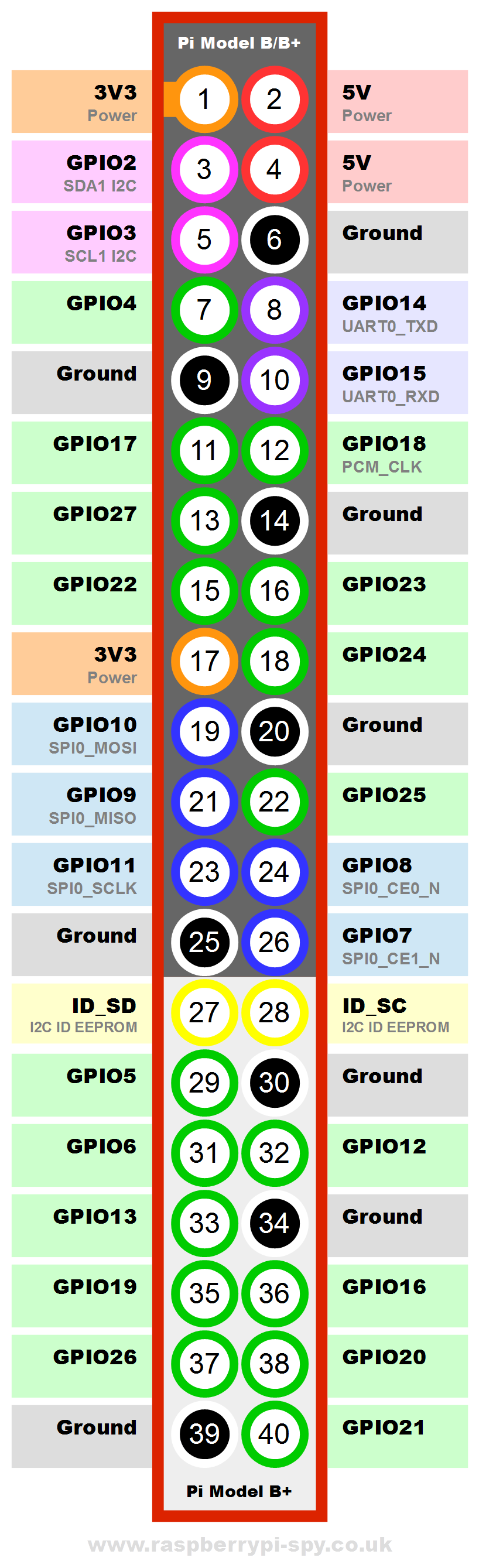
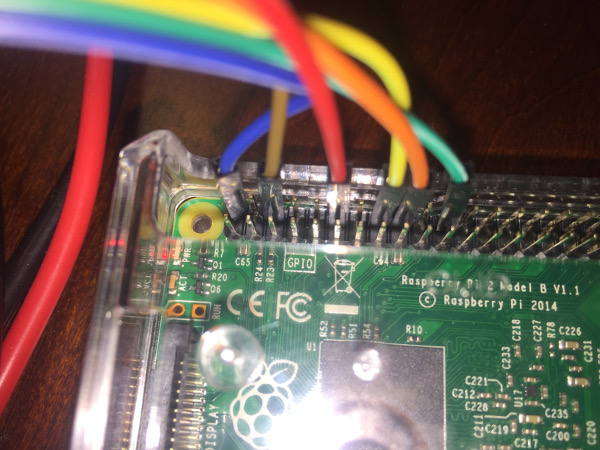
To keep things tidy and in-line I made use of the GPIO pins on the right side of the RasPi. The relay board requires 5V to operate the relay coils so the first pin to use is the top right, followed by the ground and then the Green GPIO pins: 18,23,24 and 25. Following are the random colors that I used and their respective pins.
RasPi Pinout
- (Blue) 5v
- (Brown) Ground
- (Red) GPIO18
- (Yellow) GPIO23
- (Orange) GPIO24
- (Green) GPIO25
Relay Board Pinout
- (Blue) VCC
- (Green) IN4
- (Orange) IN3
- (Yellow) IN2
- (Red) IN1
- (Brown) GND
Software
There are a number of languages and supporting libraries/frameworks to said languages that allow progromatic control of the RasPi GPIOs. For the purposes of this project, I elected to use Python and the RPi.GPIO Python library.
I am running Debian as my base distribution, so these steps may be specific to Debian (though they shouldn’t be). Also note that as of the time that this was published the latest RPi.GPIO library was 0.6.1. I also assume that you have the appropriate dependencies installed to build from source.
Step 1 - Get the tarball.
wget https://pypi.python.org/packages/source/R/RPi.GPIO/RPi.GPIO-0.6.1.tar.gz Step 2 - Decompress it and get into the directory.
tar xvfz RPi.GPIO-0.5.11.tar.gz
cd RPi.GPIO-0.5.11
Step 3 - Build and install it!
sudo python setup.py installCode and Initial Testing
One interesting thing that I found using this specific relay board is that everything is backward (or my understanding is) from most of what I find published about controlling such a board through google searches.
Quick Test - Launch a Pyton interactive shell and issue some verifying and testing commands. By issuing the following commands, assuming you are using the same RasPi and Relay Board as I am, you should see the LED and hear relay1 (IN1) switch over to the NO position when you set output to LOW and back to NC when you swithc to HIGH.
$ sudo python
Python 2.7.9 (default, Mar  1 2015, 13:48:22)
[GCC 4.9.2] on linux2
Type "help", "copyright", "credits" or "license" for more information.
>>> import RPi.GPIO as GPIO
>>> GPIO.RPI_INFO
{'P1_REVISION': 3, 'RAM': '1024M', 'REVISION': 'a21041', 'TYPE': 'Pi2 Model B', 'PROCESSOR': 'BCM2836', 'MANUFACTURER': 'Embest'}
>>> GPIO.setmode(GPIO.BCM)
>>> GPIO.setup(18,GPIO.OUT)
>>> GPIO.output(18,GPIO.LOW)
>>> GPIO.output(18,GPIO.HIGH)
>>> GPIO.cleanup()
>>> exit()
The GPIO.RPI_INFO command is not required, but may be useful to determine exactly what RasPi you have. For the model that I am using, I needed to set the BCM pin map mode so that the pins aligned with the above diagram correctly.
I mentioned that this specific setup operates in reverse of what I expected. Normally, or normally according to google searches, GPIO.output(18,GPIO.LOW) will turn OFF the relay. However, in the case of the noted relay board and raspi model it activates the NO side of the relay. Here are a few scripts that I took from GitHub and modified to work with this specific wiring and board model(s).
Turn EVERY relay on:
#!/usr/bin/python
import RPi.GPIO as GPIO

relay_pins = {'one':18, 'two':23, 'three':24, 'four':25}

GPIO.setmode(GPIO.BOARD)  # use P1 header pin numbering convention
GPIO.setwarnings(False)   # don't want to hear about how pins are already in use

for relay_pin, board_pin in relay_pins.iteritems():
        GPIO.setup(board_pin, GPIO.OUT)
        GPIO.output(board_pin, GPIO.LOW)
Turn EVERY relay off:
#!/usr/bin/python
import RPi.GPIO as GPIO

relay_pins = {'one':18, 'two':23, 'three':24, 'four':25}

GPIO.setmode(GPIO.BOARD)  # use P1 header pin numbering convention
GPIO.setwarnings(False)   # don't want to hear about how pins are already in use

for relay_pin, board_pin in relay_pins.iteritems():
        GPIO.setup(board_pin, GPIO.OUT)
        GPIO.output(board_pin, GPIO.HIGH)
Cycle through 18,23,24,25 in a cylon style, ending with all in NC position:
#!/usr/bin/python
import RPi.GPIO as GPIO
import time

sleep_time = 0.05
relay_pins = {'one':18, 'two':23, 'three':24, 'four':25}

# This works on the 2 b+ like BOARD on others, gtfo
GPIO.setmode(GPIO.BCM)

def float_pin(off, on):
        if (on != None):
                GPIO.output(on, GPIO.LOW)
                time.sleep(sleep_time);
        if (off != None):
                GPIO.output(off, GPIO.HIGH)
                time.sleep(sleep_time);

#GPIO.setmode(GPIO.BOARD)  # use P1 header pin numbering convention
GPIO.setwarnings(False)   # don't want to hear about how pins are already in use

for relay_pin, board_pin in relay_pins.iteritems():
        GPIO.setup(board_pin, GPIO.OUT)
        GPIO.output(board_pin, GPIO.LOW)

for b in xrange(2):
        float_pin(None               , relay_pins['one']  )
        float_pin(relay_pins['one']  , relay_pins['two']  )
        float_pin(relay_pins['two']  , relay_pins['three'])
        float_pin(relay_pins['three'], relay_pins['four'] )
        float_pin(relay_pins['four'] , relay_pins['three'])
        float_pin(relay_pins['three'], relay_pins['two']  )
        float_pin(relay_pins['two']  , relay_pins['one']  )
        float_pin(relay_pins['one']  , None               )
Final Thoughts
This has been quite the interesting project, if for nothing more than to see how things have changed and evolved over time (libraries and hardware) in contrast with examples and notes from people who have been here before.
In the next post I will cover how we wire in our larger relay and tie it all together with some flavor of a user interface and some error handling automation potentially. I will also discuss buildout of a projet box to put everything securely into.